Why does ‘blue mixed with yellow’ not always make green?

Of all types of mixing, we are probably most familiar with mixing paints. This becomes our point of reference for how colour behaves, instead of recognizing that the behaviour of coloured paints in mixtures is indicative of a specific type of process. Many misconceptions about the nature of colour arise when we only consider colour’s behaviour within the context of paints. We are surprised when the mixtures of sources of light are not the same as what we find in mixing paints. To understand mixing, we need understand that there are different types of mixing processes, and different media can be mixed using each type of process. The process, the specific media used and even the brand of media used all impact the final result.
It is important to recognize that we do not mix colour, rather we mix coloured media. We perceive various colours, as our visual system absorbs and interprets light distributions which enter our eyes. In each type of mixing process, the media interact with light in slightly different ways. This means that the light which is sent to our eye depends both on the mixing process and on the specific medium used. Thus the perceived colour of a mixture depends both on the process and the medium.
Subtractive Mixing Processes
1. Subtractive mixing using paints

Figure 1. Painter’s palette. (Image courtesy of Harald Arnkil.)
Paints are examples of colorants (see Figure 1), and they appear coloured because they absorb light with a certain range of wavelengths in the visible spectrum, and reflect others. Reflected light with this range of wavelengths enters our eyes and activates our visual system, resulting in a particular colour perception. When different paints are mixed together, each absorbs and reflects light with its own characteristic range of wavelengths. This results in less light being reflected from the mixture overall, as one paint will absorb some of the other paint component’s reflected light. This mixing process results in a reflected distribution of light that is dominated by wavelengths reflected by both paints.

Figure 2. Mixing phthalo blue and cadmium yellow paints.
Consider mixing blue and yellow coloured paints as an example shown in Figure 2. A blue paint reflects a light distribution with many short wavelengths, some middle wavelengths and few or no long wavelengths. Figure 3 plots a graph showing the reflected distribution of light from a blue paint, with the amount of light reflected indicated on the y-axis and wavelength on the x-axis. This type of graph is called a spectral reflectance curve, which indicates how much light is reflected at each wavelength. A yellow coloured paint often reflects a light distribution with few if any short wavelengths, and many middle and long wavelengths (see Figure 4).
When these two paints are mixed, light from the middle part of the spectrum will reflect most of all, and our visual system will interpret this distribution of light as green coloured paint (see Figure 5).


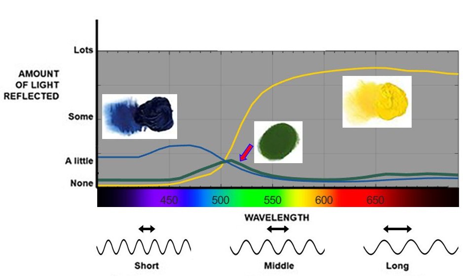
Left: Figure 3. Reflected distribution of light from a typical blue paint (cobalt blue).
Middle: Figure 4. Reflected distribution of light from a typical yellow paint (cadmium yellow light).
Right: Figure 5. When blue and yellow coloured paints are mixed, the resulting paint mixture reflects a distribution of light whose wavelengths are dominated by those commonly reflected by both paints. This process exemplifies Subtractive Mixture. Note that the exact shape of the graph depends on many factors and is depicted here as an example.
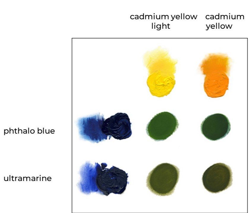
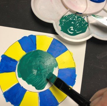
Figure 6. Mixtures of different blue and yellow coloured paints.
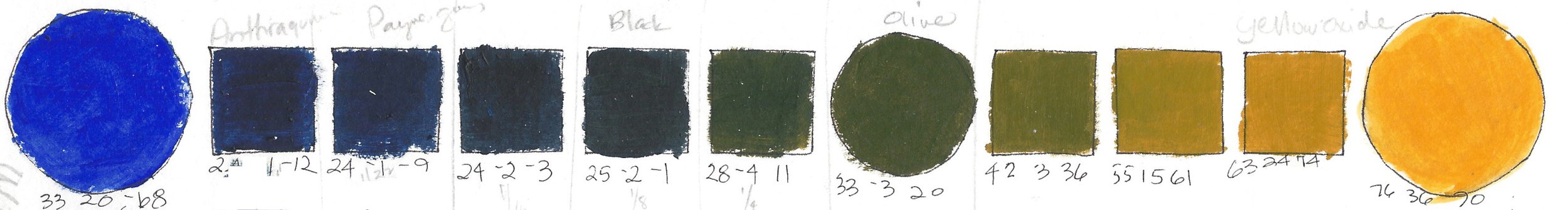
Figure 7. Mixtures from varying proportions of Ultramarine and Diarylide Yellow. (Image courtesy of Maggie Maggio.)
The graphs shown in Figures 3-5 are examples of spectral reflectance curves. Every coloured object, paint, dye, ink, etc. will absorb light with its its own particular range of wavelengths, and reflect others. An ultramarine blue paint will reflect light with a slightly different range of wavelengths compared to phthalo blue paint, so when different types of blue paint are mixed with the same cadmium yellow paint, slightly different mixed greens will result, as each mixture reflects light with a slightly different set of wavelengths (see Figure 6). Different paint manufacturers may have slightly different formulations for the same type of paint, so for example, different brands of ultramarine paints may mix to slightly different greens when mixed with the same yellow paint.
Note also that the exact proportions used will also impact the mixed colour. In some instances of mixing blue and yellow coloured paints, a near-black mixture can result. Figure 7 shows mixtures of Ultramarine and Diarylide yellow in varying proportions; a near-black is seen with approximate proportions of 7/8 Ultramarine and 1/8 Diarylide yellow.
2. Subtractive mixing using filters

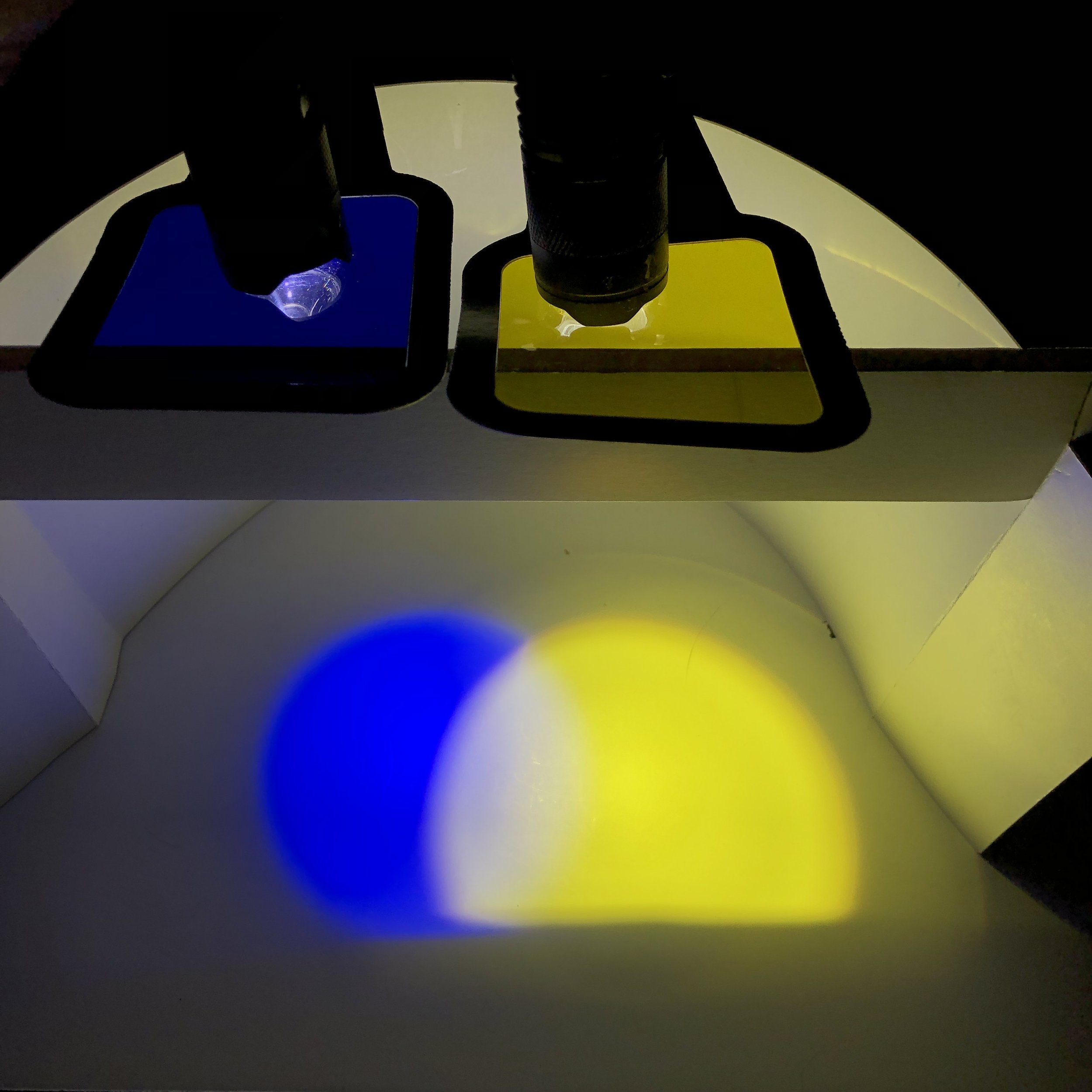
Figure 8. Subtractive Mixture. Demonstration of a single beam of white light passing through blue and yellow coloured filters, resulting in a green coloured beam of light.
Another way to demonstrate the subtractive mixing process is to send a single beam of white light through stacked blue and yellow coloured filters. In this instance, instead of a coloured paint reflecting light, a coloured filter will transmit light with a particular range of wavelengths. A blue coloured filter will transmit light’s short wavelengths most of all, and a yellow filter will transmit light with middle and long wavelengths most of all. When a single beam of light is sent through both filters, light with middle wavelengths can pass through both filters most easily, resulting in the perception of green, seen in Figure 8.
As with paints, different types and brands of filters can transmit light with varying ranges of wavelengths. Passing a beam of white light through a blue and yellow coloured filters, both with a narrow range of transmission, instead of the ones depicted in Figure 8, would result in very little light passing through the two filters, resulting in a subtractively mixed colour close to black.
Additive Mixing Processes
1. Simple additive mixing
The simple additive mixing process can be demonstrated by overlapping two coloured light beams onto a white surface. Simple additive mixing occurs when lights of different colours from two or more sources are combined (added together) before the combined light beam reaches your eye. The lights from different sources add together, and your visual system interprets all the light entering your eye as one colour perception.

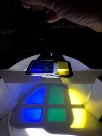
Figure 9. Simple Additive Mixture. Demonstration of two separate beams of white light passing through blue and yellow coloured filters. The overlapping area of the two coloured light beams results in a mixture of white.
Figure 9 demonstrates this, where a beam of white light is sent through a blue coloured filter, a second beam of white light is sent through a yellow coloured filter, and the two coloured light beams overlap.
In this case the overlapped areas result in a mixed colour close to white. Note that these two filters are exactly the same filters used in Figure 8, which demonstrated the subtractive mixing process. Here, the mixed colour is different because the mixing process is different. The overlapping beams of light combine or add together and send light with a distribution of wavelengths to your eyes that results in the perception of white.
2. Optical mixing
2.1 Spatial optical mixing on computer screens

Figure 10. Representation of magnifying the light sources present in pixels on a screen.
One example of optical mixing occurs as we view colours on our phone or computer screens. In these instances, the various types of displays contain individual sources of light within each pixel. The light sources typically emit light over narrow wavelength ranges centred on short, middle and long wavelengths, corresponding to blue, green and red coloured light beams. To generate different colours on a screen, each source within each pixel emits varying amounts of light, which is then interpreted by our visual system.
In Figure 10, we see the magnified pixels emitting blue coloured light in the blue area, and red and green coloured lights from the yellow area. When each pixel emits blue, green and red coloured light, as seen on the right of Figure 10, the additive mixture is perceived as white.
In a complex scene, the additive mixing of the different ratios of light emitted from the RGB sources within each pixel result in all the perceived colours in an image. There is a common misconception that additive mixtures result in vivid colours only, but the intensity or amount of light emitted from each pixel can vary. The range of pale to dark and vivid to muted colours can be produced. Figure 11 shows an image of a bowl of apples, with representations for the amounts of light emitted from each pixel shown for various colours.
Figure 11. Image of a bowl of apples, with representations for the amounts of light emitted from each pixel shown for brown, dark red, white and grey areas.
2.2 Averaging/Partitive Mixing
Some optical mixing is also known as averaging/partitive mixing. It is a form of additive mixing where combined or added sources elicit a perceptual response from our visual system. However, in this type of optical mixing, there is a dilution or averaging of the intensity of light that enters our eyes compared to simple additive mixing. This makes the mixed colours appear more muted or diluted compared to the potential vibrant mixtures found in simple additive mixing or spatial optical mixing on a computer screen. The averaging can occur either spatially, or temporally. In spatial optical mixing, individual sources of light – be they emitted or reflected – are placed next to each other. In temporal optical mixing, coloured areas are viewed in rapid successions of time, and the sources are moving too quickly to be distinguished.
Example: Spatial averaging
Figure 12 shows an example, where alternating individual stripes of blue and yellow are juxtaposed to each other. As the stripes become thinner and thinner, at some point the eye does not see them as separate sources, and their combined light enters the eye to generate the sensation of a single colour. In this case, the achromatic colour of grey is perceived.
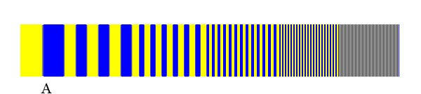
Figure 12. Spatial optical mixing. (Image courtesy of David Briggs.)
Similar to simple additive mixing, light from blue and yellow sources are entering our eyes. However, because the alternating stripes of colour are averaged over a spatial area, we see a diminished intensity of light, and the achromatic mixture is a middle grey rather than a white seen in the simple additive mixing process. This effect occurs for both emitted (e.g. your phone or computer screen) and reflected (e.g. a printed page) light sources.
Example: Blended fibres
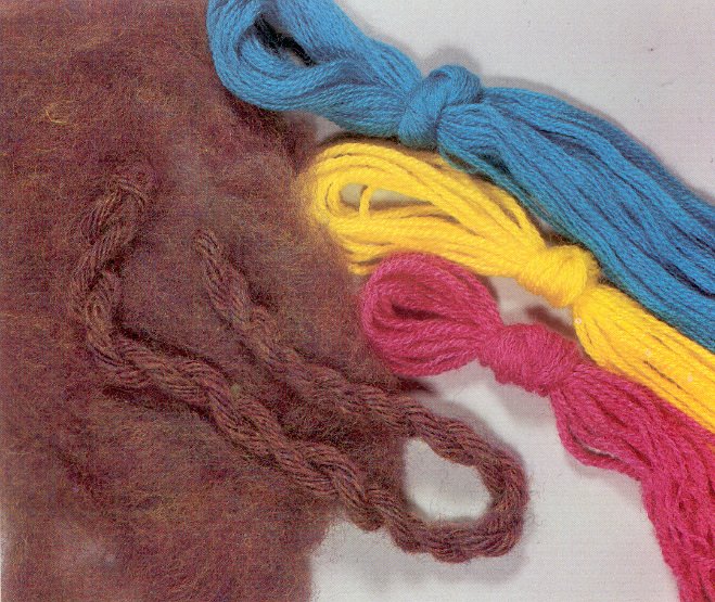
Another example of partitive/averaging mixing occurs with the blending of coloured fibres. When we blend magenta, yellow and cyan fibres (in a process called carding which precedes spinning) with different proportions, the result of the optical mixing depends on the relative proportions of the individual components, as shown in Figures 13a and b (Image source: Patricia Lambert, Mary G. Fry and Barbara Staepelaere: Color and Fiber West Chester, Pa.: Schiffer Publishing Ltd. p. 149).
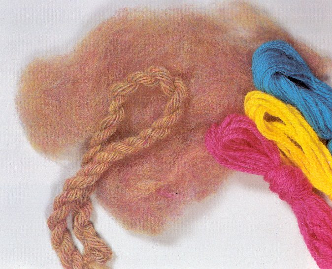
From yellow or cyan fibres, we can spin yellow and cyan yarns as seen in Figure 14 (A). When the same fibres are blended before spinning (in the carding process) the result is a green carded web as seen in Figure 14 (B), which after spinning becomes a green yarn seen in Figure 14 (C). However, when the same fibres are spun first and the single cyan and yellow yarns are twisted into a ply yarn seen in Figure 14 (D), the two component colours can be seen individually.
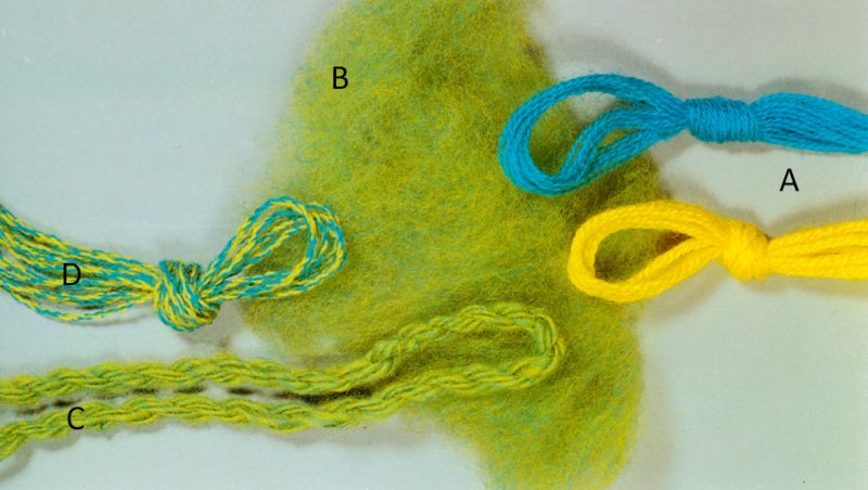
Figure 13. Partitive mixing of colours fibres in yarn. Image source: Patricia Lambert, Mary G. Fry and Barbara Staepelaere: Color and Fiber West Chester, Pa.: Schiffer Publishing Ltd. p. 152.
Example: Pointillist painting
In pointillist painting, the image is formed by tiny dots of paint that at a large enough distance cannot be seen individually, thus forming a partitive mixture. However, at the usual viewing distance, the dots do not always completely fuse, creating a unique visual effect that has been described as “a soft and peculiar brilliancy” (Ogden Rood, Modern Chromatics, 1879). Figure 15a shows a section of one of the best-known pointillist paintings: A Sunday Afternoon on the Island of La Grande Jatte (Un dimanche après-midi à l'Île de la Grande Jatte) by Georges Seurat, painted from 1884-1886. Figures 15b and c are further magnifications of the image, showing the varying size of the individually painted dots. In some areas the dots are small enough for true partitive mixing to occur, but in most areas the dots are larger and in places form clearly distinguishable dashes.


For more information on the colour theory of pointillist (and divisionist) painting see David Briggs’ discussion on pointillist mixing, Robert Hirschler’s article on Colour Theory and Neo-impressionist Landscapes (pp. 20-32), and a lecture by Robert Hirschler on Colour Theory and Neo-impressionist Painting.
Example: Temporal averaging
Another process that generates optical colour mixtures via additive/partitive mixing is a rapidly spinning disk, where each section of the disk is painted in different or alternating colours. This is an example of temporal optical mixing, where the disk spins so fast we cannot see the individual areas of colour. Rather the combined light reflected from various sections of the spinning disk enters our eyes. In this type of mixing, the intensity of the reflected light is averaged, and we perceive mixed colours which appear muted, and possibly grey depending on the choice of yellow and blue components. The exact choice and proportions of painted colours on the disk will impact the mixed colours. Even pale pink is a possible mixed colour from a reddish-blue and yellow areas on a spinning disk!
Figure 13. Example of temporal optical mixing. This spinning disk optically mixing to a pale grey. (Source: Figure 4.4.4 from Additive-averaging mixing by David Briggs.)